CNC MILLING / CUSTOM COMPONENTS

CNC Milling Services

Housings, precision plates and mounting components. Pockets, faces and hole patterns machined around the interfaces in your assembly.

POCKETS. WALLS. LOCATING FEATURES.

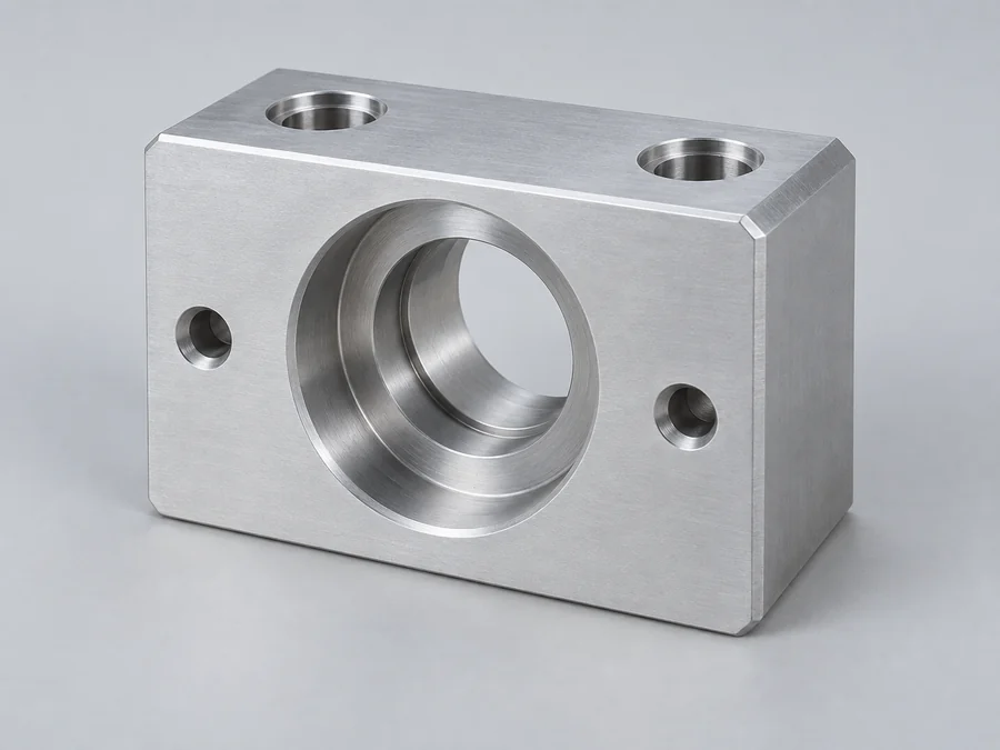
Look closer at a milled component.

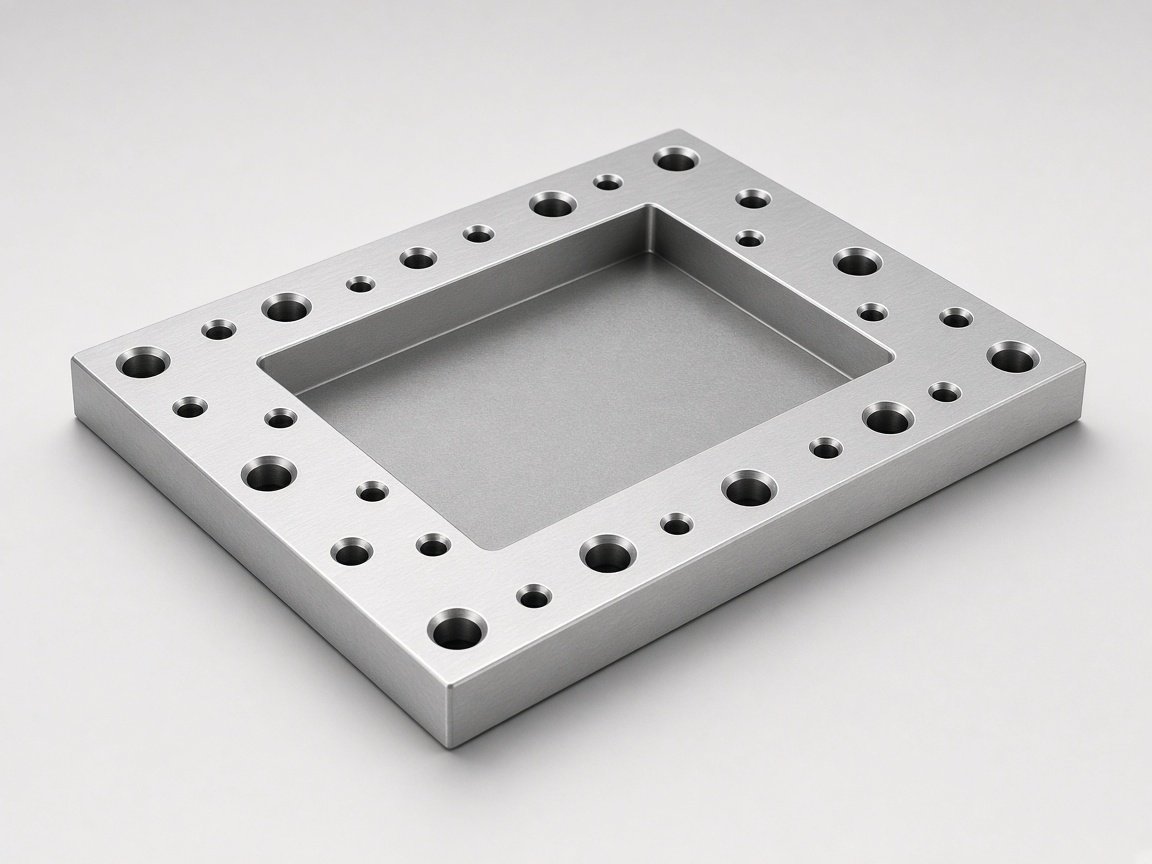
A pocket holds the assembly. A shoulder locates it. A hole pattern connects it. The relationships between these features define the part.

Aluminum fixture plate with a recessed pocket and mounting holes

THE GEOMETRY BEHIND THE PART

Pocket / locating face / mounting pattern

01

The space inside

Show pocket depth, internal corner radii and access to recessed features. Include the component that must fit inside when useful.

POCKETS & INTERNAL FEATURES

02

The surfaces that locate

Identify the datum faces and the dimensions between mounting, sealing and locating surfaces.

DATUMS & MATING FACES

03

The pattern that connects

Define hole positions, counterbores and threads relative to the functional references on the drawing.

HOLES & THREADS

BEFORE THE TOOLPATH

Four details worth reviewing early.

Send the functional requirements with the complete model. These features deserve a closer look before the machining scope is agreed.

01 / TOOL ACCESS

Deep pockets.
Tight internal corners.

Identify depth, radii and any areas with restricted access. Mark where the geometry is fixed by the mating component.

Include: depth, corner radii and mating geometry.

02 / PART SUPPORT

Thin walls.
Delicate sections.

Show the wall sections that control function and the faces where appearance matters. Distinguish essential dimensions from general geometry.

Include: wall thickness and critical surfaces.

03 / FEATURE RELATIONSHIPS

Features on
different faces.

Use common drawing references to describe how side holes, pockets and mounting faces relate to one another.

Include: datums and positional requirements.

04 / FINAL CONDITION

Fits after
surface treatment.

State which requirements apply to the completed part. Identify cosmetic faces, masked areas and any added hardware.

Include: finish and final dimensional requirements.

Feasibility and accepted requirements are confirmed for the specific geometry, material and quantity.

MATERIAL TO FINISHED SURFACE

Specify the part as it will be used.

Include the material grade and final surface condition in the same enquiry. Finishing requirements can affect functional and cosmetic surfaces.

Material requirements

Material family

Grades to specify

Aluminum

6061 / 7075

Grade, condition and cosmetic faces

Stainless steel

304 / 316

Grade and surface requirements

Carbon & tool steel

Drawing-specified grade

Condition and any heat treatment

Engineering plastics

POM / PEEK

Grade, environment and application

Grades shown are examples for enquiry. Material availability and suitability are confirmed during quotation.

SURFACE & SECONDARY WORK

Finish follows function.

Mark cosmetic faces, masked areas and any inserts or hardware. Confirm the finish and additional operations in the quotation.

MILLING QUESTIONS

A few details
before you send.

Files, feature limits and finishing requirements for a custom milled part.

Send a STEP or STP model and a dimensioned PDF where available. Include the part revision, material, order quantity, surface requirements and any dimensions that control assembly or function. If only one file format is available, send it with a short description of the part.

Include these features in the complete model and identify any dimensions that cannot change. Tool access, wall support, material and workholding need to be assessed together. Feasibility and any suggested changes are confirmed after drawing review.

Tolerance and size suitability depend on the part geometry, material and machining setup. Provide overall dimensions and mark the critical fits and datums. The quotation confirms the requirements that can be accepted for your specific component.

List the required finish, cosmetic faces, masking, inspection points and documents in the enquiry. These are reviewed as part of the finished-part scope, with availability and delivery requirements confirmed in the quotation.

YOUR NEXT MILLED PART

Send the drawing.
Let’s define the scope.

Share the model and the requirements that matter. Include what is ready now and add the remaining details during review.

01

Drawing & revision

STEP / STP model and a dimensioned PDF.

02

Material, finish & quantity

Include critical fits and your required date.

03

Quotation & next steps

Feasibility, price, lead time and inspection scope confirmed after review.

REQUEST A QUOTE

Tell us about your project.

Regarding: CNC Milling

Attach drawings when you send your email.

error: Content is protected !!